Capability
In-House
Tool Development.
Die design, DFM analysis, mould flow simulation, and in-house tool qualification — from T0 trials to PPAP sign-off. Shorter sample cycles and fewer design iterations before series production.
Overview
Tool Development
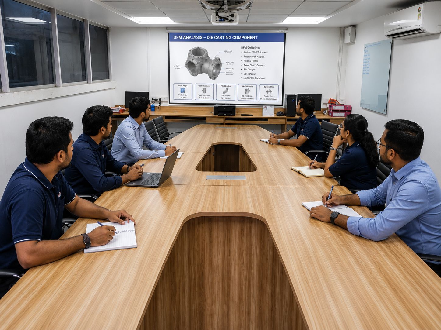
New component programmes begin before a single tonne of aluminium is cast. SAPL's tool development process starts with a thorough DFM (Design for Manufacturability) review — examining wall thickness, draft angles, parting line position, gate and runner location, and potential sink or porosity risk areas before the die is designed.
After DFM sign-off, we design the die in 3D CAD and run mould flow simulation to predict fill pattern, potential cold shut locations, and air entrapment. Changes at the simulation stage cost nothing. Changes after tool fabrication cost time and money. Catching problems early is the commercial rationale for simulation.
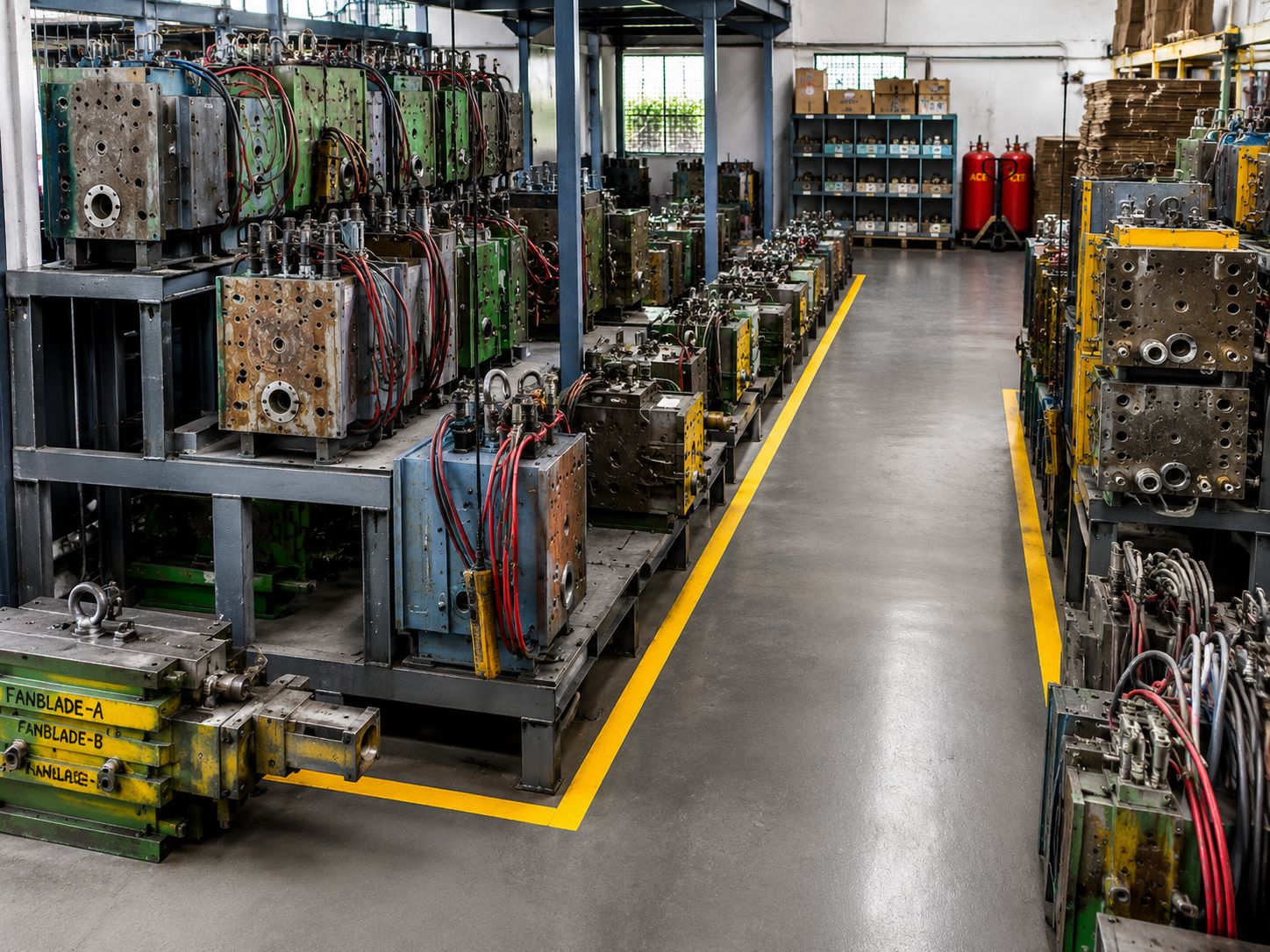
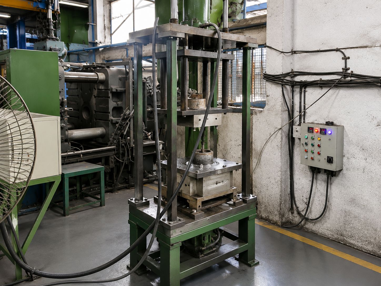
Dies are fabricated in H13 tool steel and qualified through T0, T1, and T2 trial runs. T0 samples establish baseline dimensional capability. T1 and T2 correct any dimensional deviations and optimise process parameters. Full PPAP documentation is available for automotive and precision industrial programmes.
Process
How it works
DFM Review
Engineering analysis of customer CAD. Written DFM report with marked-up drawing identifying: draft angle issues, thin walls, parting line recommendation, gate location, and sink risk areas.
Die Design
3D CAD die design — cavity, cores, slides, ejector system, cooling channel layout, gate and runner design. Design review with customer before fabrication.
Mould Flow Simulation
Fill simulation predicts flow front behaviour, temperature distribution, air pockets, and potential cold shut locations. Gate and runner geometry adjusted before cutting begins.
Die Fabrication
H13 tool steel machined by EDM and CNC milling. Surface hardness and finish per specification. Cavity polished to required surface finish grade.
T0 Trial & Dimensional Check
First shots taken. Full dimensional report against customer drawing. Process parameters recorded. Deviation map identifies areas for correction.
T1/T2 Correction & PPAP
Dimensional corrections applied. T1 samples re-measured. PPAP documentation compiled — including dimensional results, material certificates, process capability, and control plan.
Applications
Industries and use cases
Components produced via this process are supplied to OEMs and Tier-1 manufacturers across these sectors.
New Component Programmes
Any HPDC or GDC component where SAPL is involved from the design or pre-production stage
Design Transfer
Existing components transferring from another die caster — die audit, DFM review of existing design, new tool if required
Engineering Changes
ECN-driven die modifications — weld repair, insert, or new tool depending on change magnitude
Related
Connected capabilities
High Pressure Die Casting
Five fully-automatic HPDC machines from 180T to 450T.
View capability →Engineering Support
DFM analysis, alloy selection guidance, design review, and prototype samples — before drawings are frozen and tooling is cut.
View capability →Contract Manufacturing
From raw casting to finished, inspected, and packed component — under one roof, one management team, one Certificate of Conformance.
View capability →Get Started
Discuss your component with our engineering team
Share your drawings — STEP, IGES, DXF, PDF, or SolidWorks. We'll review manufacturability, recommend the right process and alloy, and respond with a detailed technical and commercial assessment within 72 hours.